Identifying bridge deformation using laser scanning data

Identifying bridge deformation using laser scanning data
Linh Truong-Hong1, Roderik Lindenbergh1
1 Dept. of Geoscience & Remote Sensing, Delft University of Technology, Delft, Netherlands, (l.truong; r.c.lindenbergh@tudelft.nl)
2 Dept. of Research and Development (R&D), VMT Solutions. (l.truong@)
Keywords: Bridge deformation; vertical clearance; laser scanning; point cloud; cell grid
ABSTRACT
Increasing traffic weights and aggressive environmental conditions may result in unexpected deterioration of a bridge’s components. Particularly, most bridges in Europe and US over half life span are affected by such impact. Structural deficiencies may cause partial or full collapse of bridges resulting in problems for human life, economy, society, and environment. As such, deformation monitoring of the bridge’s components has high priority in bridge inspection and assessment. Laser scanning has been used to capture the three-dimensional (3D) topographic surface of structures accurately and efficiently, which can be subsequently used to measure change of the structures. This paper introduces three approaches called point-to-surface (P2S), point-to-cell (P2C), and cell-to-cell (C2C) to measure the deformation of a structure using laser scanning data. This study also investigates the impact of the quality of a point cloud and selected surface or cell size to the achieved accuracy of deformation detection, which will be demonstrated through implementation to measure the bridge’s vertical clearance, which is the maximum vertical drop distance from the bottom of the bridge deck to the ground or water level.
I. INTRODUCTION
With a designed 50-year lifespan, most bridges in US and Europe is subject to structural deficiencies (ASCE 2017; Pakrashi et al. 2011) because of excessive usage, overloading, material aging, and environmental impacts. As such, changes in a bridge structural components should be timely reported for maintaining a safe, functional, and reliable structure. The impact of such changes to structural integrity may manifest as alterations in the condition of the connections, deformations, distortions or embedment loss. Current bridge inspection procedures mainly rely on visual inspection with physical inspectors associated with special equipment on site, which has several downsides: (1) subjective results; (2) slow and expensive procedure; (3) high risk for inspectors and (4) traffic closures (Metni et al., 2007; Phares et al. 2004). Laser scanning is emerging as an alternative method to collect data for the bridge inspection, as this technology can capture the current geometry of the structures accurately and efficiently. That is particularly compatible for measuring changes or deformation of structures (Lindenbergh et al., 2015). Thus, this paper focusses on processing laser scanning data (obtained by terrestrial or mobile laser scanning) to measure structural deformation, and as a case study, it is discussed and shown how vertical clearance estimated are obtained.
II. RELATED WORKS
For the last decade, many methods have been proposed to analyse a point cloud acquired from aerial and terrestrial laser scanning for change detection or deformation measurement (Mukupa et al., 2016). For example, Girardeau-Montaut et al. (2005) proposed a cloud to cloud (C2C) method to measure deformation through a distance from a point in the reference surface to its nearest neighbour point in the sampling surface. Additionally, to improve accuracy of the C2C method, the least square fit was used to estimate a local surface of the sampling surface at the given point through its neighbour points, and the deformation is the distance from the point of the reference surface to the local surface. Moreover, Lague et al., (2013) proposed the multiscale model to model cloud comparison (M3C2) for change detection from laser scanning. In this method, a normal vector of each point of the reference surface was first computed from its neighbour points. Next, at a given point of the reference surface, the cylinder with a predefined radius and the directional vector as the normal vector of the point was establish to extract sub-points of the reference and sampling surface. The local distance between two surfaces was defined as a distance between average positions of two sub-clouds. These methods are efficiently in determining change detection from massive data rather than giving high accuracy as the accuracy depends on a normal vector of the points subjected to point density and a noise level of the data set (Girardeau-Montaut et al., 2005; Lague et al., 2013). Particularly, those methods are mainly used for topographic change detection. This section is restricted to methods for structural deformation measurements, particularly for a bridge structure, while a systematic overview of the application of TLSs for bridge engineering has been published elsewhere [e.g. (Truong-Hong et al., 2014)].
Laser scanning has been used to measure overall displacements of a bridge (Lichti et al. 2002; Lovas et al., 2008; Zogg et al., 2008), vertical clearance (Riveiro et al., 2013; Liu et al., 2012), and deformations/distortions of each member (Truong-Hong et al., 2015). A deformation describes change of the surface in different instants (e.g. t0 and t1). For example, in structural engineering, the deformation is defined as the distance between a surface at an epoch i (known as an undeformed or reference surface) and a surface at an epoch j (a deformed or sampling surface). In those applications, Kretschmer et al. (2004) and Truong-Hong et al. (2014) measure structural changes (vertical clearance and displacement) through a distance from a point of the sample surface to its projection on the reference surface. The projection was done based on a normal vector of a local reference surface determined from local neighbor points of the projection points derived from the reference surface. In another data processing direction, Lichti et al. (2002) measure vertical displacement of wood stringers by comparing fitting lines of the top and bottom stringers subject to unloaded and loaded conditions. Similarly, Riveiro et al. (2013) fitted a point cloud of a beam camber and pavement by a polynomial curve and a plane, respectively. Then, the vertical clearance of a bridge was as difference of z values computed from the curve and the plane. Finally, Paffenholz et al. (2008) subdivided a point cloud into 2D cell-grids with a cell size of 0.25m, and used the median of z coordinates of each cell to determine vertical displacements. Truong-Hong et al. (2015) also used a cell-based approach to measure vertical displacements of a beam as the distance between average z coordinates of the points within the cell to a reference surface.
III. METHODOLOGY
As laser scanning typically captures massive topographic data sampling a structures’ surface, estimating structural deformation based on a point-to-point assessment is time consuming and impractical. In addition, of the presence of noise and/or mixed pixels also affect the estimation quality, particularly when millimeter accuracy is required. To address such issues, three methods are presented in this paper: point-to-surface (P2S), point-to-cell (P2C), and cell-to-cell (C2C), for which the workflows are shown in Figure 1. In addition, from a point of view of structural analysis, deformation of a structure involves directional and total deformation. However, to determine total deformation at a specific location in a structure directly from laser scanning data may be impractical: the structures surface should be captured at identical locations in different scans and epochs while extracting points representing the same location on the structure in different epochs in case of massive data may well be impossible. As such, the deformation mentioned here is a vertical deformation or displacement.
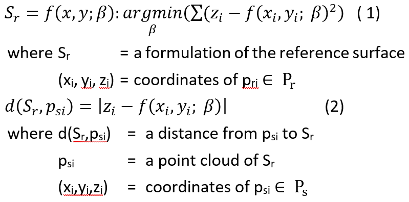
After scanning and registering all point clouds into a single coordinate system, input point clouds of interest are classified into reference and sampling data sets (Pr and Ps), respectively, describing the structures at different moment (or epochs). Pr represents the structure’s surface (called a reference surface, Sr), which is often subjected to small deformation or easily to identify a close-form formulation of the surface. Ps describes the structure surface (called a sampling surface, Ss) subject to large deformation. In the P2S approach, the shape of Sr is theoretically known a priori, and a close form of Sr is defined by an optimal fitting surface as expressed in Eq. 1. However, if the close form is not available, an optimization should be applied to identify the best fitting surface, in which the root mean squares error (RMSE) can be an indicator. In this approach, the directional (or vertical) deformation at a specific location on the structure is a distance from the data points psi Î Ps to Sr, which is given in Eq. 2.
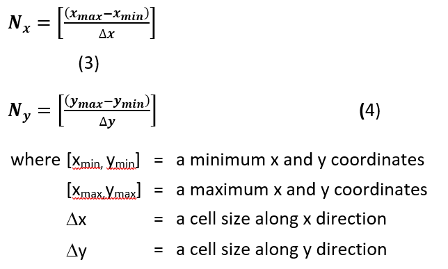
In the P2C and C2C methods, a 2D cell grid is employed to divide a bounded, 2D region of the data sets into a set of uniform cells. The process started to initially project the data set onto a plane of interest (PoI), for example an xy plane in a global coordinate system. Each cell is represented by an index Cij, where i Î [1, Nx] and j Î [1, Ny], where Nx and Ny are the number of cells along x and y direction, as expressed in Eq.s 3 and 4. Each cell Cij has two lists for indexing Pr and Ps, as notated by Cij,r and Cij,s, respectively. This data management allows easy retrieval of the points (pij,r and pij,s) in Cij from Pr and Ps.
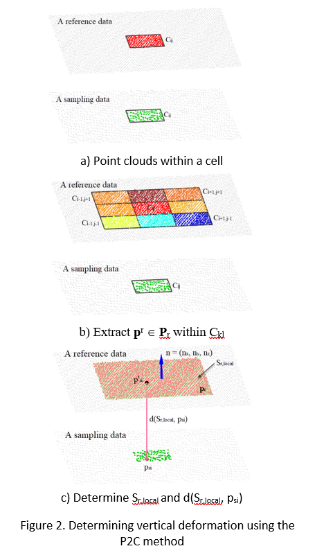
In the P2C method, the vertical deformation is defined as the distance from a point psi Î Ps to an intersection point between a vertical ray through psi and Sr (Truong-Hong et al., 2015). This assumption is based on the observation that the structural deformation between epochs is often small, while lateral displacement can be neglected. In this method, a local planar surface Sr,local is used instead of Sr, which is estimated as follows: (1) from the cell Cij containing the point psi, a set of cells Ckl (k = [i-1, i+1] and l = [j-1, j+1] is extracted (Fig. 2a and b); (2) pr Î Pr are extracted from Ckl. Then, a robust principal component analysis (PCA) (Laefer et al., 2017) is employed to determine the surface normal n = (nx, ny, nz) of Sr,local (Fig. 2c) from the covariance matrix C, as expressed in Eq. 5 and 6. Finally, vertical displacements are determined using Eq. 2.
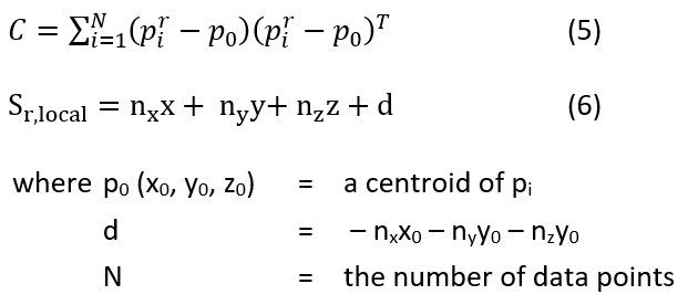
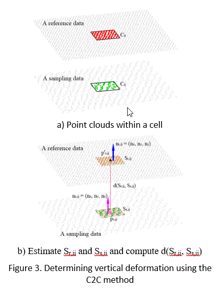
In the C2C method, it is assumed that Sr and Ss at the specific location are respectively represented by the local planar surfaces Sr,ij and Ss,ij. This implies that Sr and Ss can be represented by local planar surfaces at cells in the cell grid. Thus, for each cell Cij, the local planar surfaces, Sr,ij and Ss,ij are respectively estimated from ps,ij Î Ps and pr,ij Î Pr within Cij using PCA, as expressed in Eq. 5 and 6 (Fig. 3). The vertical deformation is herein defined as the directional distance between the centroid point of ps,ij on Ss,ij to an intersection point (called p’s,ij) between a vertical ray through psi and Sr,ij, as given in Eq. 2.
IV. CASE STUDY
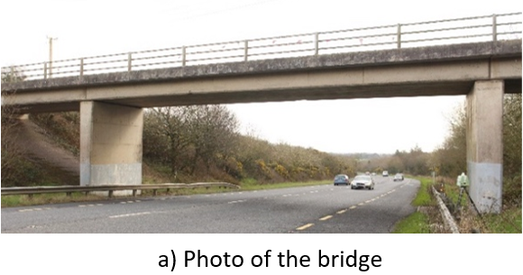
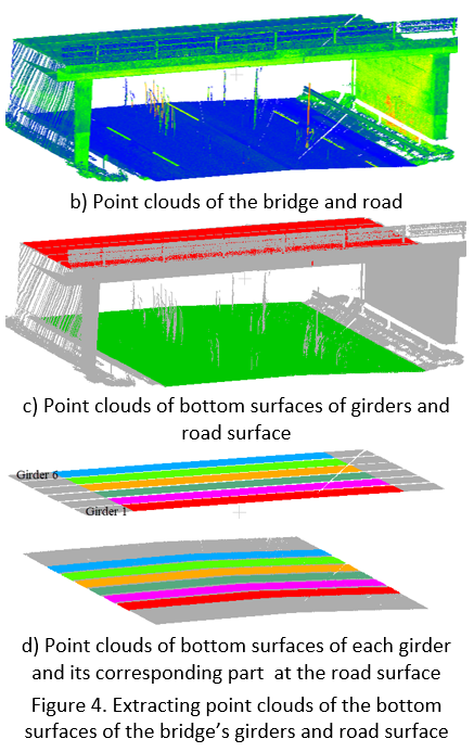
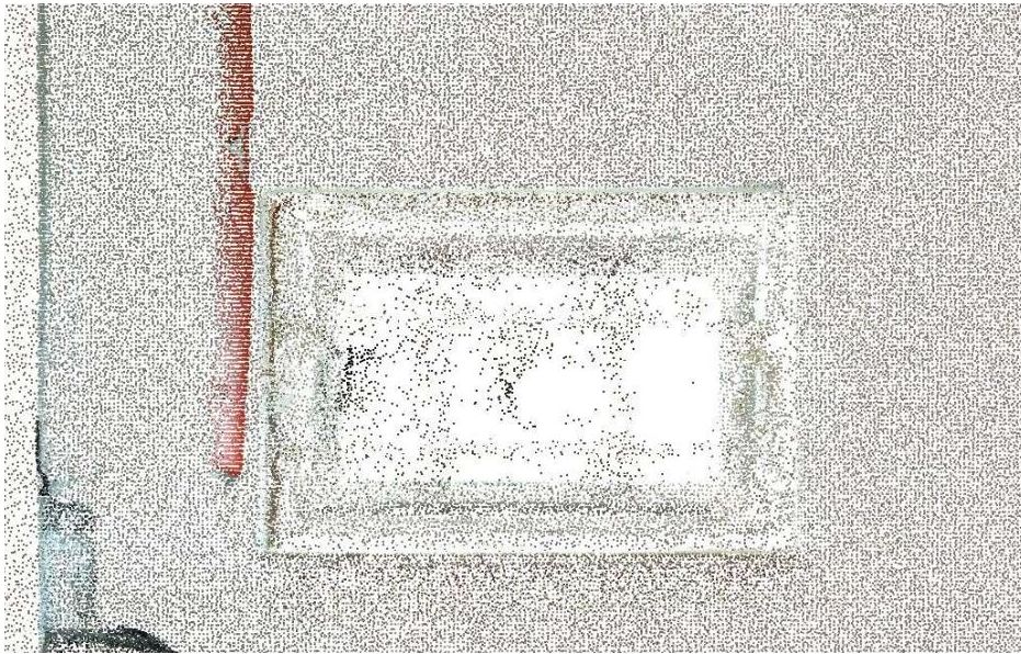
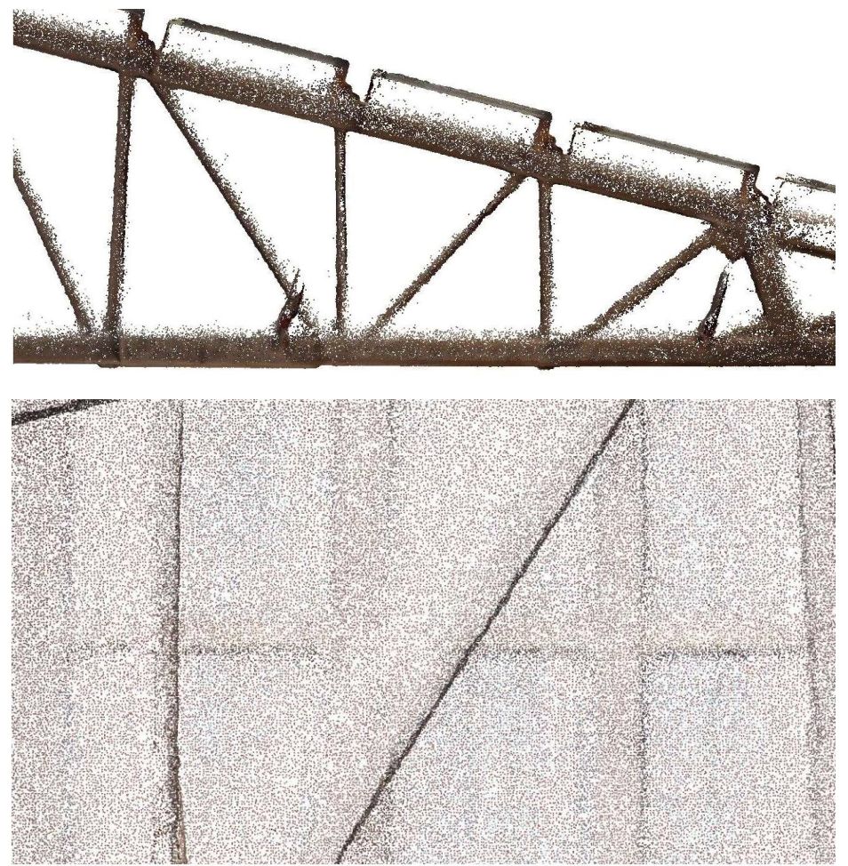
The proposed methods are demonstrated by measuring the vertical clearance of an overpass bridge at the intersection between N25 and Coolballow Rd., Co. Wexford, Ireland (Fig. 4a). Data for the bridge and road were acquired by a Leica P20 TLS unit with a sampling step of 3.1 mm at a range measurement of 10 m (Fig. 4b). The average distance from the scanner to the bridge deck was around 15m. An octree-based region-growing approach (Vo et al., 2015) was employed to extract the point clouds of the bottom fibers of bridge’s girders and of the road (Fig. 4c), which were considered as the reference and sampling data sets, respectively. As the vertical clearance is a goal of this example, only the point clouds of the road surface and the bottom fibers of the girders within the intersection of the convex hulls of the two data sets were used. Moreover, the point cloud of the bottom girder was separated using a clustering algorithm. For this purpose DBScan (Ester et al., 1996) was used (Fig. 4d), for which the input parameters, the maximum distance between two points (e) and the minimum number of points (minPts) were selected as 0.4m and 20 points, respectively.
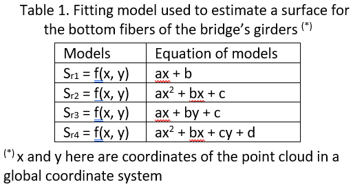
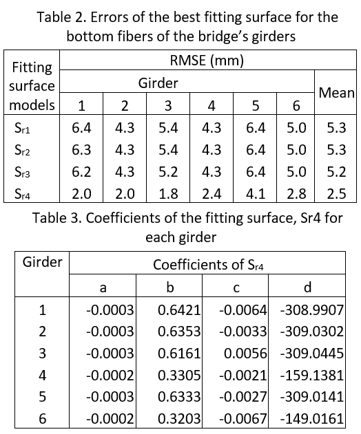
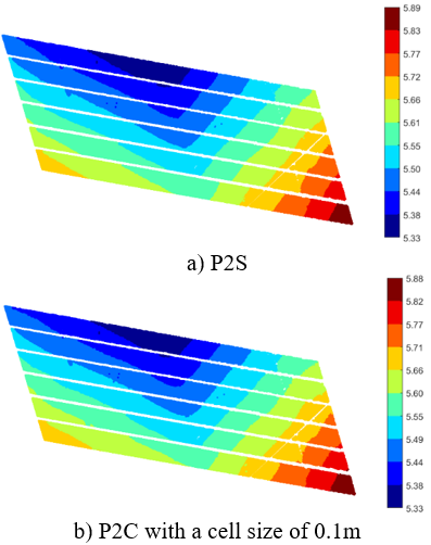
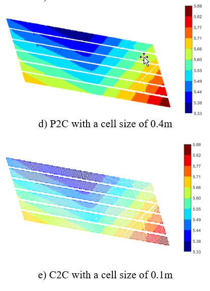
For applying the P2S method, a fitting 3D surface was employed to fit the bottom fibers of the girders or the reference surface. However, depending on the design and construction of the bridge, some scenarios may apply: (1) the elevation of each girder may be different; (2) the bottom surface of the girder is unknown, which may be a planar or parabolic surface due to a camber or deflection of the girder. As such, different types of surfaces (Table 1) were proposed to fit the reference surface for each girder separately and the best fit model was determined based on the minimum RMSE (Table 2). Note that to prevent over-fitting, about 70% of random points of the reference surface were used to predict the fitting surface while the remaining points were used to validate the fitting model. Based on the RMSE, the fitting surface model, Sr4 was chosen, and coefficients of the fitting model for each beam are shown in Table 3. Finally, the vertical clearance values were computed based on Eq. 2 and results are shown in Fig. 5a.
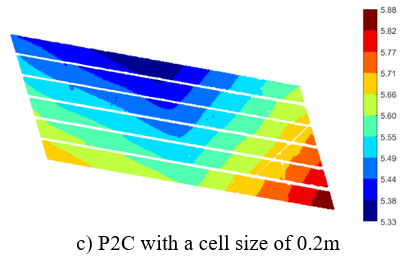
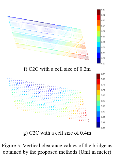
In the P2C and C2C methods, the cell grid was employed to decompose an initial 2D bounding box of both reference and sampling data sets into uniform cell grids, in which the cell size is of key importance. However, this value is often empirically selected. As such, cell sizes of 0.1m (C1), 0.2m (C2) and 0.4m (C3) were used to investigate the impact of the cell size on the results. Moreover, a robust PCA method (Laefer et al., 2017) was employed to estimate a normal of Sr,local in the P2C method and of Sr,ij and Ss,ij in the C2C method (Fig.s 3 and 4). Then, the vertical clearance was estimated based on Eq. 2. Results are shown in Fig. 5b-d for the P2C method and Fig.s 5e-g for the C2C method.
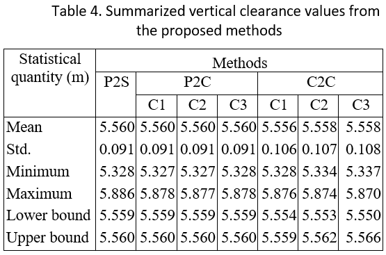
Results show consistence between contours of vertical bridge clearance values derived from the proposed methods (Table 4 and Fig. 5). Particularly, in this case study, the vertical displacements from the P2S method slightly differ from those from the P2C method, even when a cell size of 0.4m is used in the P2C method. Morever, the average of the vertical clearance values from the C2C method is slightly smaller than those from the other methods, and this mean is about 3.2mm (P2S vs. C2C_C1) (Table 3). Although the maximum and minimum of the results from the 3 methods differ up to 8.9mm (PS2 vs. P2C_C2) and 16mm (P2S vs. C2C_C3), with a 95% confidence interval, bounds of the vertical clearance values are less than 1.0mm (P2S vs. P2C) and 9.3mm (P2S vs. C2C_C3).
This case study shows that these consistently vertical clearance values can be obtained by the three proposed methods. However, when using the P2S method, it is a challenge to determine the best fit model of the reference surface since the close-form of this surface is unknown. Particularly, when a structure is in service and subject to damage, describing a best fit surface as a smooth surface may not describe accurately the reference surface because local damage/deformation may exist. In addition, the P2C and C2C methods provide straightforward procedures to estimate vertical clearance. However, a challenge for these methods is the selection of the cell size, such that the local surface can represent accurately the reference surface at a specific location. In theory, the cell size could adapt to the local curvature of the surface, in which the cell size is small when the surface has a small curvature, and vice versa. Thus, in practice, the P2C and C2C methods are recommended since they are simple methods and do not require heavy computation for a large data set.
Another important issue is to select reference data or a reference surface from the data sets because the accuracy of the fitting surface representing the reference surface is also one of the key impacts when estimating vertical clearance. For example, when the road surface in this case study is chosen as reference surface while the bottom surfaces of a bridge’s girders is fixed as the sampling surface, results may change. To test this, a similar procedure as above was used for the 3 methods (P2S, P2C and C2C), where the cell size of 0.2m was used for the P2C and C2C methods. In the P2S method, the best fit surface obtained is Sr = -0.0026x2 + 5.238y – 0.041y – 2568, with a RMSE by 23.9mm. Resulting vertical clearance values are shown in Fig. 6.
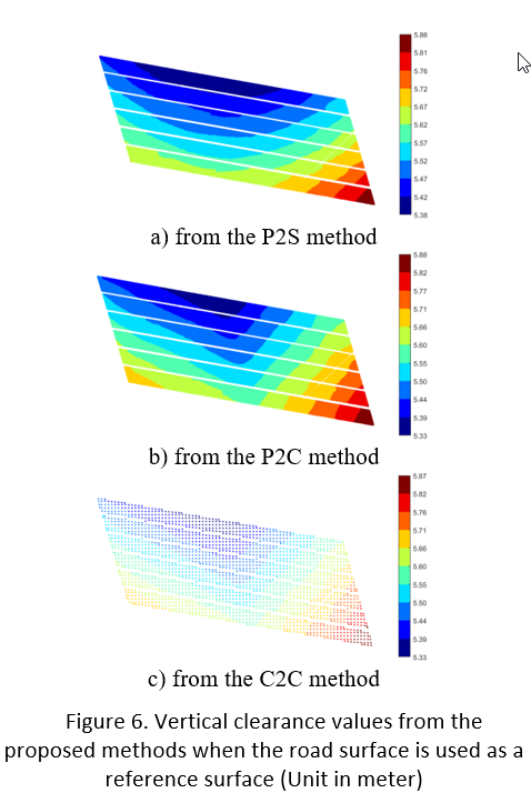
When the road surface is considered as the reference surface, patterns of vertical clearance values from the P2S method differ from the ones derived when using the bottom surface of the bridges girders as the reference surface (Fig. 5a vs. Fig. 6a). With a 95% confident interval, the difference between the two vertical clearance estimations can reach 47.5mm, in which the lower bounds of the vertical clearance in this case was 5.564m. On the other hand, the vertical clearance estimations resulting from the P2C and C2C methods, show no significant difference when the reference surface is changed: the maximum difference is 5.1mm for the mean value of the vertical clearance derived from the P2C method (Fig. 6b and c). Therefore, it is roughly concluded that the selection of the reference surface strongly impacts the estimated vertical deformation when using the P2S method while the other two methods are only slightly affected.
V. CONCLUSIONS
Measuring deformation of structures is a key factor in structural assessment. Contact methods can produce high accuracy results; however, the methods also have several limitations, for example measuring only at specific location of the structure and high costs. Laser scanning enables capture entire surfaces of the structure accurately and efficiently. That offers an alternative approach to measure deformation of the structure. This paper proposed and evaluated three processing methods, called point-to-surface (P2S), point-to-cell (P2C) and cell-to-cell (C2C) to estimate the deformation of a structure based on laser scanning data. Through a case study of bridge vertical clearance estimations, where the bottom surface of a bridge’s girders was considered the reference surface, is shown that slight differences occur between those methods. The difference in the mean estimated value of the vertical clearance is no more than 3.2mm (P2S vs. C2C_C1). Interestingly, in this case study, for the P2S method, the cell size seemly does not affect the vertical clearance of the bridge. On the other hand, it is shown that the P2S method is sensitive to the choice of reference surface or best fiting surface However, the choice of reference surface does not seem to impact both the P2C and C2C. As a conclusion, the P2C and C2C methods are recommend to measure deformation of the structure, particularly in case of large point clouds. Reason is these methods are simple, low-cost, and do not require prior knowledge on a close-form of the reference surface. However, these methods require a predefined cell size, which could be selected based on the curvature of the reference surface.
Acknowledgements
This work was funded by the generous support of the European Commission through H2020 MSCA-IF, “BridgeScan: Laser Scanning for Automatic Bridge Assessment”, Grant 799149. The first author is also grateful for the support of the UCD Seed funding for the project “Laser Scanning for Automatic Bridge Rating”, grant SF1404 in data acquisition.
References
ASCE (2017). 2017 Infrastructure Report Card: Bridge.
Ester, M., H.P. Kriegel, J. Sander and X. Xu. (1996). A density-based algorithm for discovering clusters in large spatial databases with noise. Second International Conference on Knowledge Discovery and Data Mining, 2-4 August, Portland, Oregon, USA.
Girardeau-Montaut, D.; Roux, M.; Marc, R.; Thibault, G. (2005): Change detection on points cloud data acquired with a ground laser scanner. International Archives of Photogrammetry, Remote Sensing and Spatial Information Sciences, 36(part 3), 30–35.
Kretschmer, U., T. Abmayr, M. Thies, and C. Fröhlich (2004). Traffic construction analysis by use of terrestrial laser scanning. In: Proceedings of the ISPRS Working Group VIII-2 Laser scanners for forest and landscape assessment.
Lague, D.; Brodu, N.; Leroux, J. (2013): Accurate 3D comparison of complex topography with terrestrial laser scanner: Application to the Rangitikei canyon (NZ). ISPRS Journal of Photogrammetry and Remote Sensing, 82, 10–26.
Laefer, D.F., and L. Truong-Hong (2017). Toward automatic generation of 3D steel structures for building information modelling. Automation in Construction 74:66-77.
Lichti, D.D., S.J. Gordon, M.P. Stawart, J. Franke, and M. Tsakiri (2002). Comparison of digital photogrammetry and laser scanning. In: Proc. International Society for Photogrammetr and Remote Sensing, pp. 39-44. 2002.
Lindenbergh, R.C. and P. Pietrzyk (2015). Change detection and deformation analyis using static and mobile laser scannin. Applied Geomatics 7: 65-74.
Liu, W., S. Chen, and E. Hasuer (2012). Bridge Clearance Evaluation Based on Terrestrial LIDAR Scan. Journal of Performance of Constructed Facilities 26 (4):469-477.
Lovas, T., A. Barsi, A. Detrekoi, L. Dunai, Z. Csak, A. Polgar, A. Berenyi, Z. Kibedy, and K. Szocs (2008). Terrestrial laser scanning in deformation measurements of structures. ISPRS congress, 3-11 July, Beijing.
Metni, N., and T. Hamel (2007). A UAV for bridge inspection: Visual servoing control law with orientation limits. Automation in Construction 17 (1):3-10.
Mukupa, W.; Roberst, G. W.; Hancock, C. M.; Al-Manasir, K. (2016). A review of the use of terrestrial laser scanning application for change detection and deformation monitoring of structures. Survey Review, 49(353), 99-116
Paffenholz, J., H. Vennegeerts, and H. Kutterer (2008). High Frequency Terrestrial Laser Scans for Monitoring Kinematic Processes. UNGEO 2008-4th International Conference on Engineering Surveying, October 23-24, 2008, Bratislava, Slovakia.
Vikram, P., E. O’Brien, and A. O’Connor (2011). A review of road structure data in six European countries. In: Proceedings of the ICE-Urban Design and Planning 164 (4):225-232.
Phares, B.M., G.A. Washer, D.D. Rolander, B.A. Graybeal, and M. Moore (2004). Routine highway bridge inspection condition documentation accuracy and reliability. J Bridge Eng 9 (4):403-413.
Riveiro, B., H. González-Jorge, M. Varela, and D.V. Jauregui (2013). Validation of terrestrial laser scanning and photogrammetry techniques for the measurement of vertical underclearance and beam geometry in structural inspection of bridges. Measurement 46:784-794.
Truong-Hong L., and D.F. Laefer (2014a). Using Terrestrial Laser Scanning for Dynamic Bridge Deflection Measurement. Istanbul Bridge August 11-13, 2014, Istanbul, Turkey
Truong-Hong, L., and D.F. Laefer (2014b). Application of Terrestrial Laser Scanner in Bridge Inspection: Review and an Opportunity. 37th IASBE Symposium, Sep 3-5, Madrid, Spain.
Truong-Hong, L., and D.F. Laefer (2015). Documentation of bridges by terrestrial laser scanner. IABSE Symposium Report, 13-15 May, Nara, Japan.
Vo, A.V, L. Truong-Hong, D.F. Laefer, and M. Bertolotto. (2015). Octree-based region growing for point cloud segmentation. ISPRS Journal of Photogrammetry and Remote Sensing 104:88-100.
Zogg, H.-M., and H. Ingensand (2008). Terrestrial laser scanning for deformation monitoring – Load tests on the Felsanau Viaduct. ISPRS Congress, 3-11 July, Beijing, China.
Nguyen Huynh (Rainer)
")
About the Author:
Nguyen Huynh (Rainer) is Managing Director at VMT Solutions, specializing in Point Cloud to BIM workflows for surveying, planning, and engineering offices. He focuses on precise BIM models, clearly defined quality standards, and long-term technical partnerships.
Share This Story!
Related Posts
Recent Posts


We are proud to have
satisfied customers.
 Gerd Gindullis, Lecturer for digital as-built data capture at Aachen University of Applied Sciences, TerraMeta 3D Laser Service
 Stefan Schramm, Architekt Stefan Schramm
„Your plans are perfect; I’ve never seen anything like this before. These are drawings of the highest quality, I must say. I want to express my sincere thanks once again for your work.“
 Endre Szokolai, Digitalplan-Szokolai
VMT modeled a large industrial building in 3D for our research project. We provided DWG plans to VMT, and they delivered a highly detailed model, including the building envelope, interior walls, openings, and stairs. We had previously contracted a German company for the same object, but unfortunately, it didn’t work out. I was relieved and pleased that VMT handled it so reliably. Thank you for the excellent work and the truly fair price!

Very reliable company, courteous staff, and top-quality work. Our plans were created quickly and accurately. Thank you for that. Highly recommended.

Excellent advice and high 3D modeling quality at a great price-performance ratio… What more could you want? I can highly recommend them…