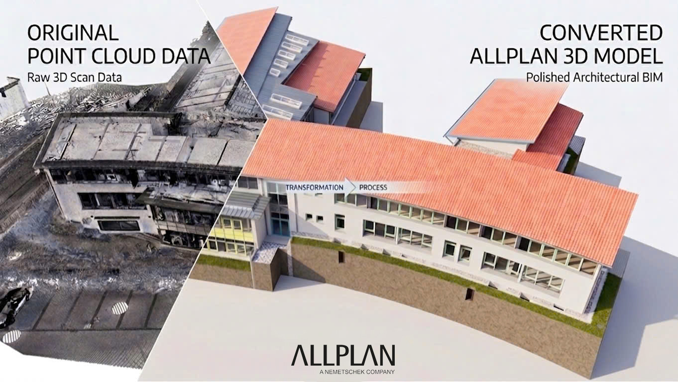
Surveying offices and engineering firms working with 3D laser scanners today deliver precise raw data to their clients — dense point clouds that capture every element, every wall, every floor level with millimeter accuracy. But between that scan data and a usable BIM model lies a step that rarely succeeds in-house: native modeling in Allplan.
Many offices load the point cloud and then face the same obstacles — capacity bottlenecks, limited Allplan expertise, or delivery timelines that stretch too long. The result: the client waits, and the full potential of the scan goes unrealized.
This article explains what a complete point cloud to BIM Allplan workflow looks like, which LOD levels are realistically achievable, and what actually matters in native modeling.
👉 Learn more about our Scan-to-BIM services
Table of Contents
What Does “Native Modeling” in Allplan Mean?
The distinction is important because it marks a fundamental difference in what the client receives.
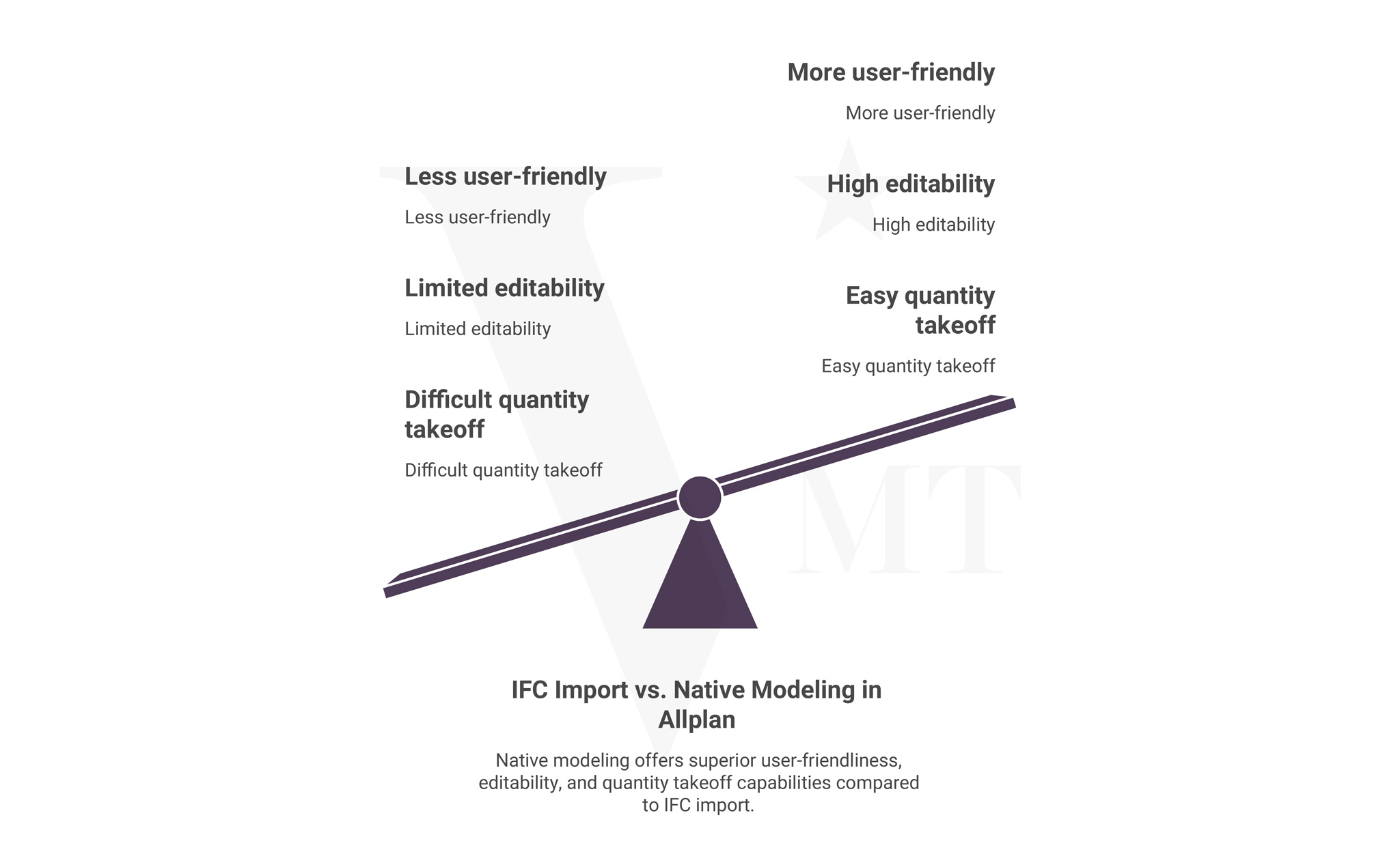
An IFC-based handover means a model is built in a different application — Revit or Archicad, for example — and then exported as an IFC file. Allplan can open that file, but the result is not an editable Allplan project. Elements are not parametric, attributes are not correctly linked, and any adjustment requires considerable rework.
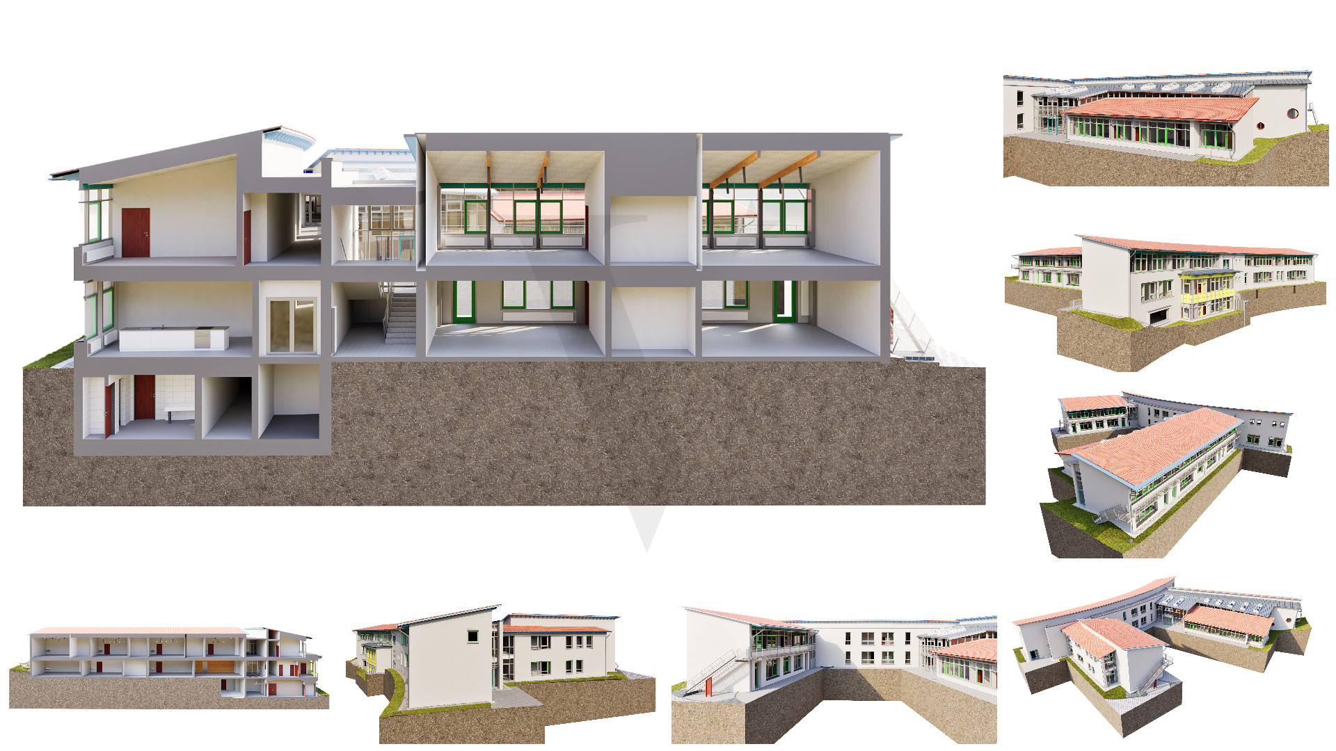
Native Allplan modeling means the model is built from the start in Allplan — using Allplan building elements, Allplan attributes, and a project-specific folder structure. The client receives a fully editable .npz project file that integrates seamlessly into their existing Allplan workflows.
For surveying and planning offices that use Allplan as their primary platform, this difference is significant. A native model is immediately usable — for as-built documentation, renovation planning, tendering, or facility management.
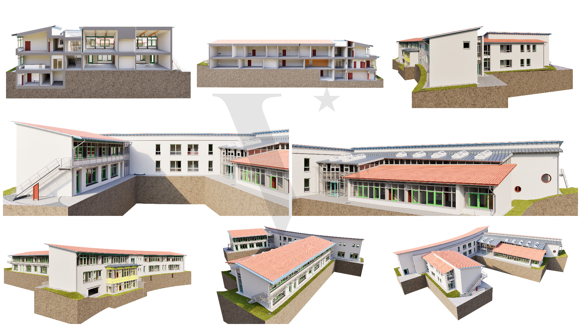
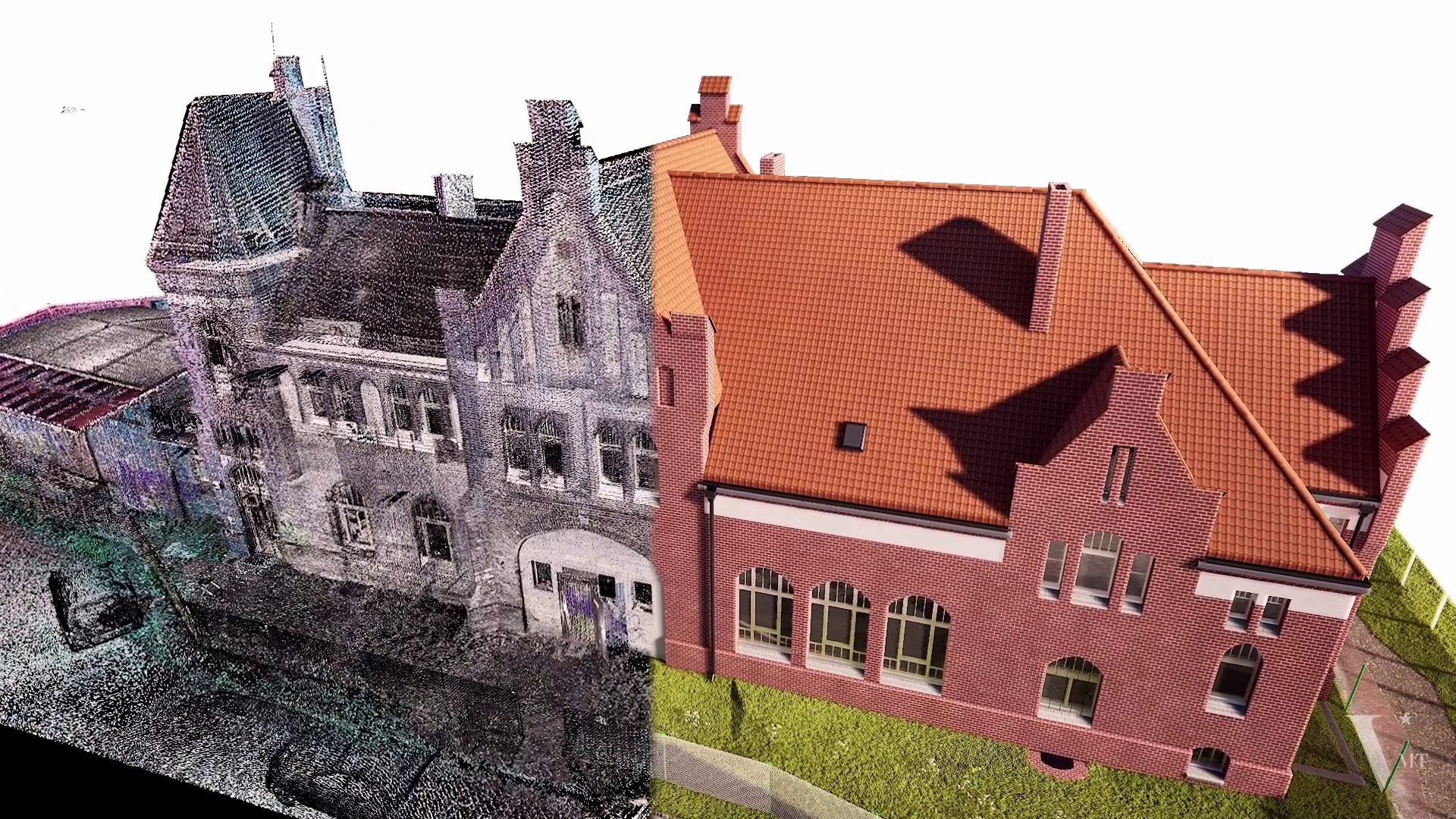
Step by Step: The Point Cloud to Allplan BIM Workflow
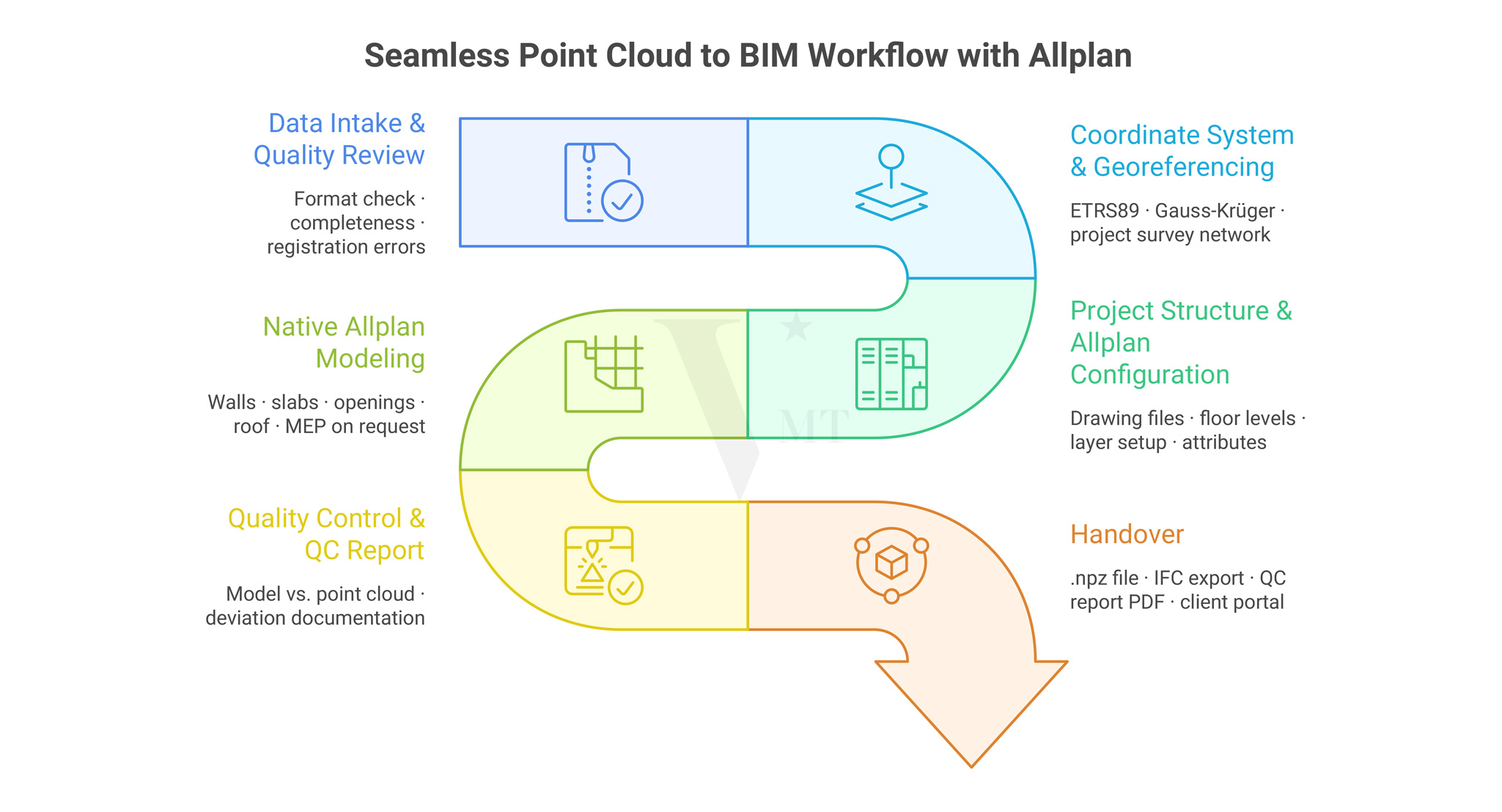
Point Cloud to Allplan Workflow – a structured scan-to-BIM process from data validation to model delivery
1. Data Intake and Quality Review
Before modeling begins, the delivered point cloud is reviewed carefully. This goes beyond checking the file format — E57, RCP, LAS, or XYZ — and covers the completeness of the captured data.
Typical review checkpoints:
- Are all relevant floor levels captured?
- Are there registration errors between individual scan positions?
- Are critical areas — stair cores, recesses, facade offsets — sufficiently represented?
- Does the point density meet the requirements of the agreed LOD level?
If gaps or inconsistencies are identified at this stage, we communicate them before modeling starts. Corrections discovered after delivery cost time and erode trust.
2. Coordinate System and Georeferencing
Point clouds from geodetically controlled surveys typically carry a defined coordinate system — ETRS89, Gauss-Kruger, or a project-specific survey network. This system is carried directly into the Allplan project so that the BIM model is correctly positioned in both plan and elevation.
This is particularly relevant when the model will later be combined with geodata, site plan documents, or other planning references.
3. Project Structure and Allplan Configuration
Before modeling begins, the project structure is set up in Allplan — drawing files, floor levels, layer structure, and attribute assignments. This configuration follows the client’s office standards or an agreed handover protocol.
A clean project structure is the prerequisite for the model to open and be used by the recipient without any adjustment effort.
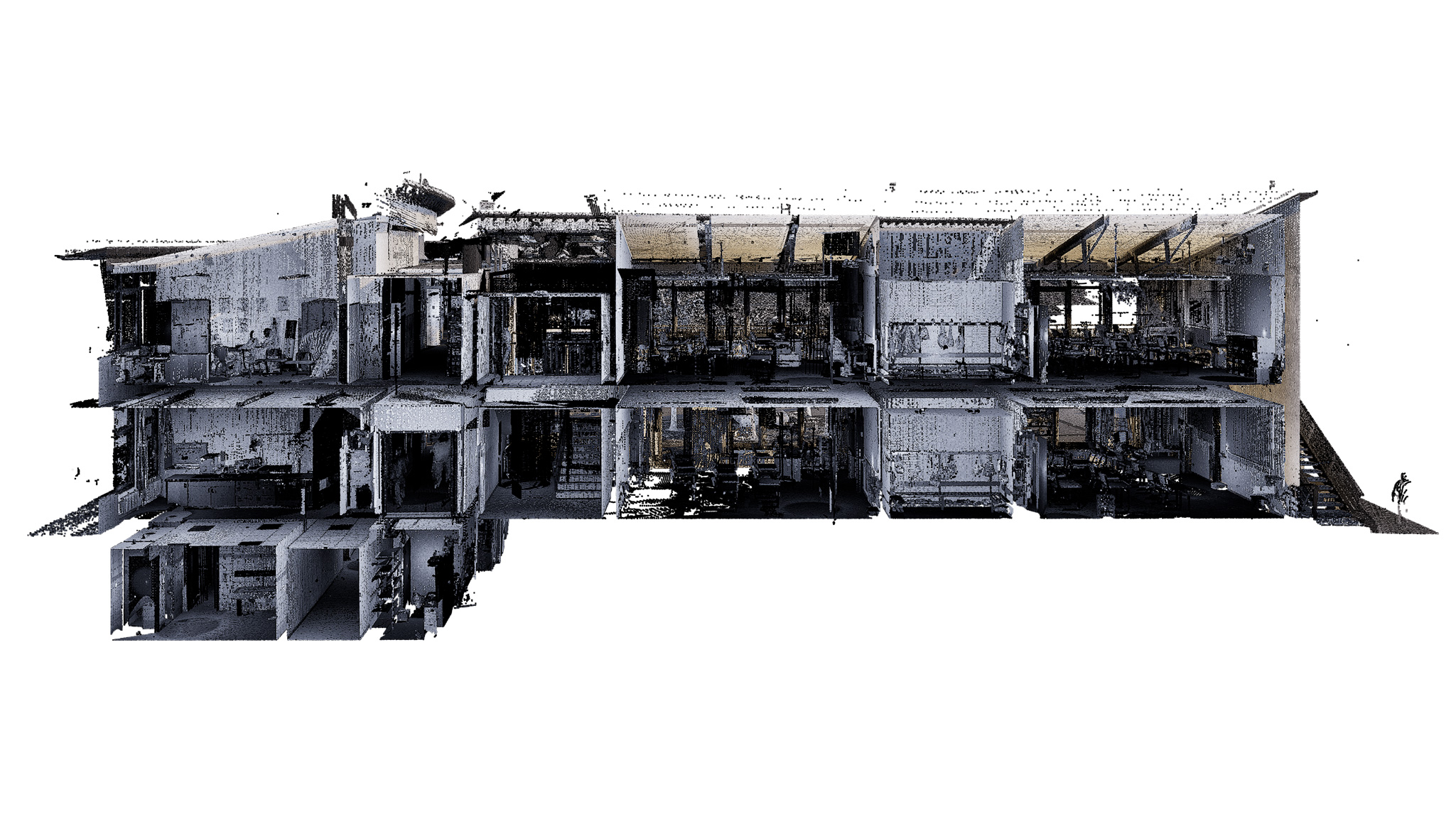
4. Modeling from the Point Cloud
The actual modeling is carried out in Allplan, with the point cloud referenced directly. Depending on the agreed LOD level, the following elements are captured:
Architecture / Building Structure:
- Walls, columns, slabs, roof structures
- Window and door openings including reveal details
- Stairs, ramps, parapets
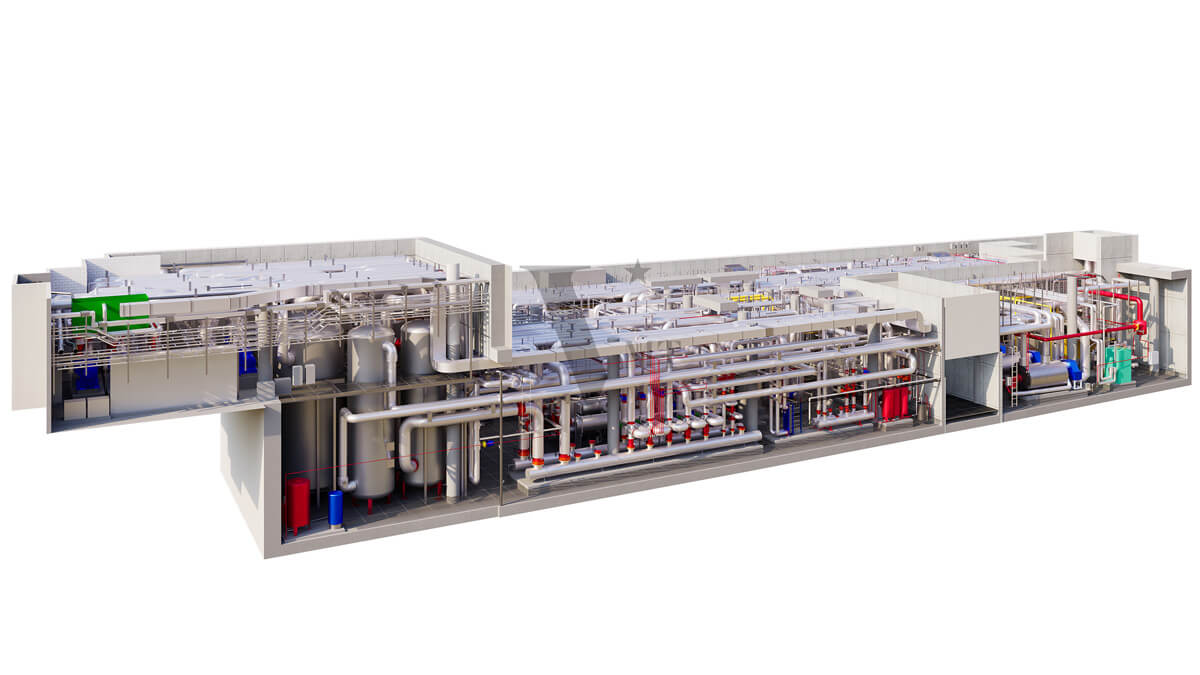
Building Services (on request):
- Pipe runs, shafts, duct routes
- Equipment and piping systems in industrial projects
Site and Surroundings:
- Terrain model derived from point cloud data
- Access surfaces, embankments, retaining walls
Every element is modeled to the agreed LOD level. Geometry is derived exclusively from what is measurable in the point cloud — not from assumed or interpolated dimensions.
5. Quality Control and QC Report
Once modeling is complete, the Allplan model is systematically checked against the point cloud. Deviations are documented, tolerance thresholds are defined, and a QC report is produced and handed over alongside the model file.
This report is not only a quality record — it also documents where the point cloud itself was incomplete and which assumptions were made as a result.
6. Handover
Standard project handover includes:
- Allplan project file (.npz) in the agreed version
- IFC export on request
- QC report as PDF
- Brief documentation of the project structure
Delivery is via the VMTS client portal, WeTransfer, or a secure file transfer channel on request.
LOD Levels in Allplan: What Is Realistically Achievable?
LOD — Level of Detail or Level of Development — describes how precise and information-rich a BIM element is. For point cloud to BIM Allplan projects, the following benchmarks apply:
| LOD | Content | Typical Use Case |
|---|---|---|
| LOD 200 | Mass elements without exact dimensions | Early-phase planning, rough cost estimation |
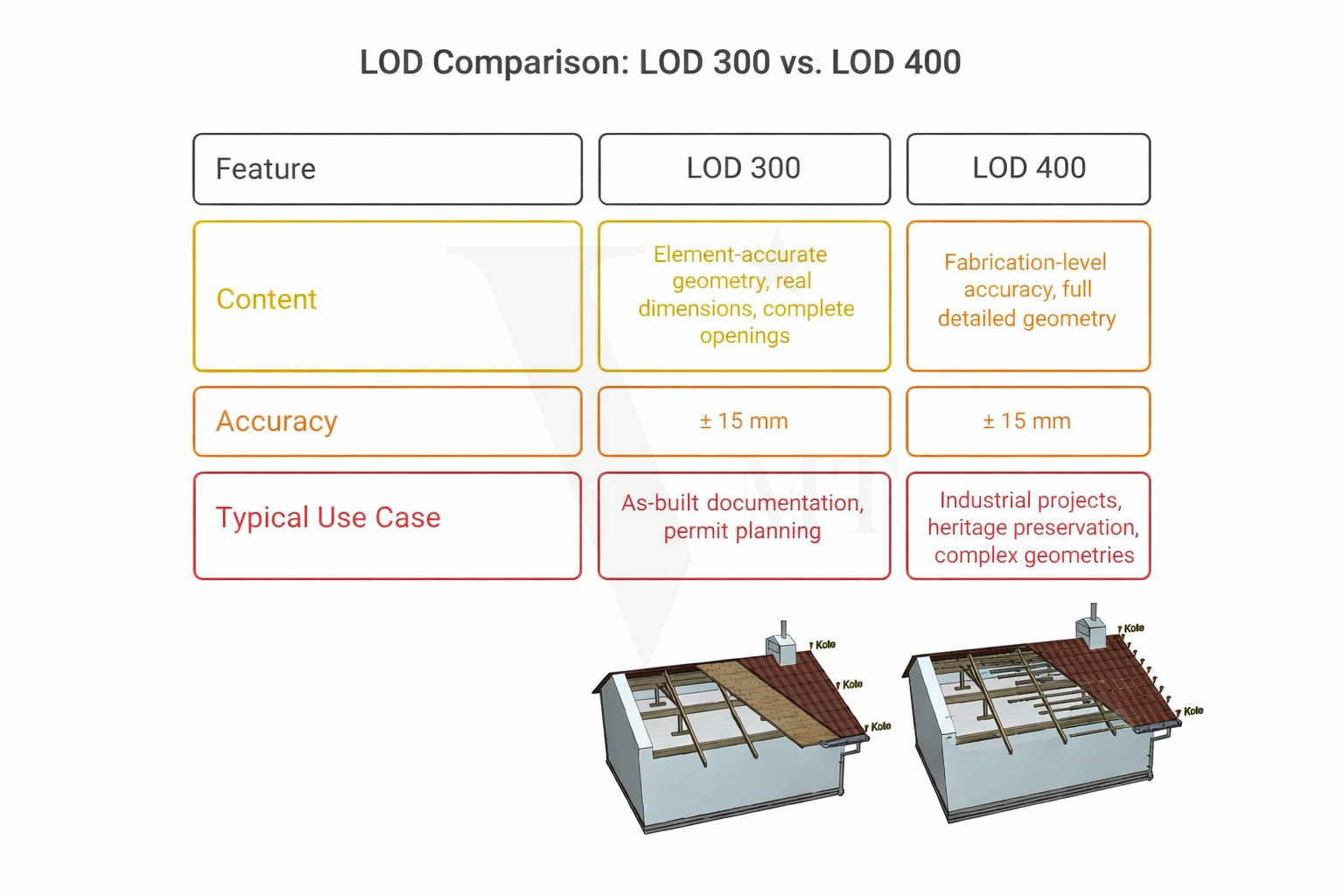
| LOD 300 | Element-accurate geometry, real dimensions, complete openings | Design and permit planning, as-built documentation |
| LOD 350 | As LOD 300, with connection details for other trades | Coordination model, interdisciplinary planning |
| LOD 400 | Fabrication-relevant accuracy, full detail geometry | Industrial projects, heritage preservation, complex geometry |
For most as-built surveys and renovation projects, LOD 300 is the practical standard. For historic buildings with irregular geometry, structural deformation, or historic construction methods, an LOD 300 model with supplementary LOD 400 detail in selected areas is often the appropriate approach.
One point to note: the achievable LOD depends directly on the quality of the point cloud. Insufficient scan resolution or incomplete capture limits model accuracy — regardless of how carefully the modeling is carried out.
Common Challenges — and How We Handle Them
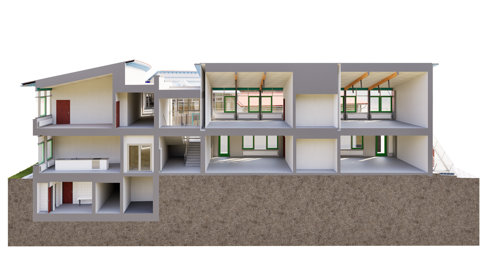
Complex roof geometries Historic roof structures with irregular rafter lengths, deformation, or later additions place high demands on the modeler. We model these areas from the actual point cloud geometry, document deviations, and recommend supplementary scan coverage where needed.
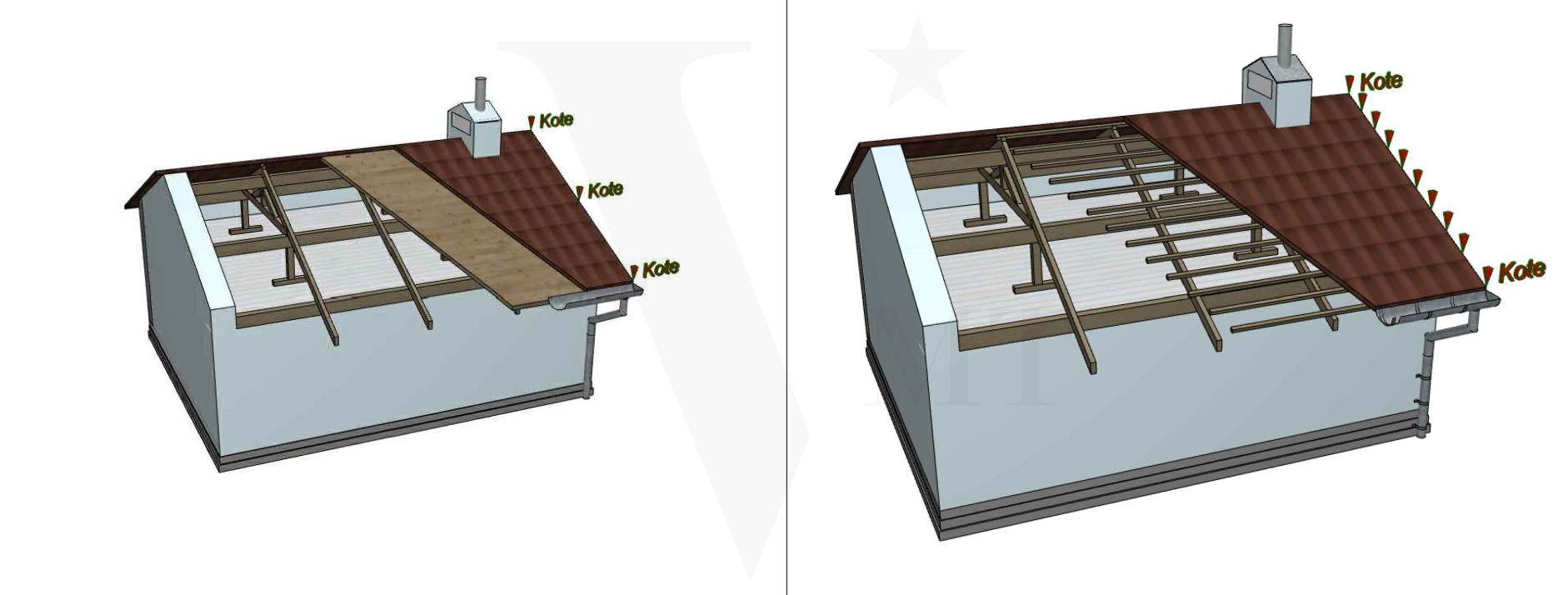
Detailed modeling of complex roof geometries in Allplan based on point clouds (LOD 300–400)
Limited scan visibility Areas behind furniture, inside service shafts, or beneath suspended ceilings are frequently incomplete in the point cloud. In these cases we work with geometrically plausible assumptions — always transparently noted in the QC report.
Multiple building sections with different scan dates Where building sections were scanned at different times, coordinate systems can drift slightly. We check registration accuracy at the start of each project and resolve open questions before modeling begins.
Version and format compatibility Allplan projects are version-specific. We deliver in the Allplan version the client is currently using, and document any conversion requirements clearly.
Why Native Allplan Modeling Makes a Practical Difference
- No conversion effort. The project file opens directly — no IFC reimport, no relinking required.
- Full editability. Every element is a genuine Allplan object with all the properties Allplan expects. Adjustments are possible without additional effort.
- Consistent attribute structure. Room designations, layer compositions, element properties — everything is set up the way Allplan expects it. Quantity take-offs and plan output work immediately.
- A familiar working environment for your team. Your planning team opens an Allplan file and works in the environment they know. No learning curve, no queries.
VMTS as Your Allplan Modeling Partner
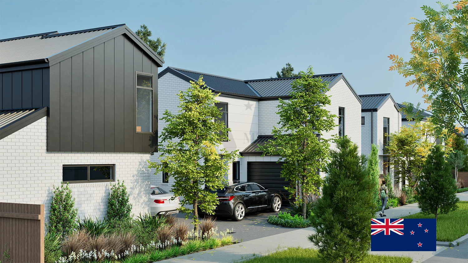
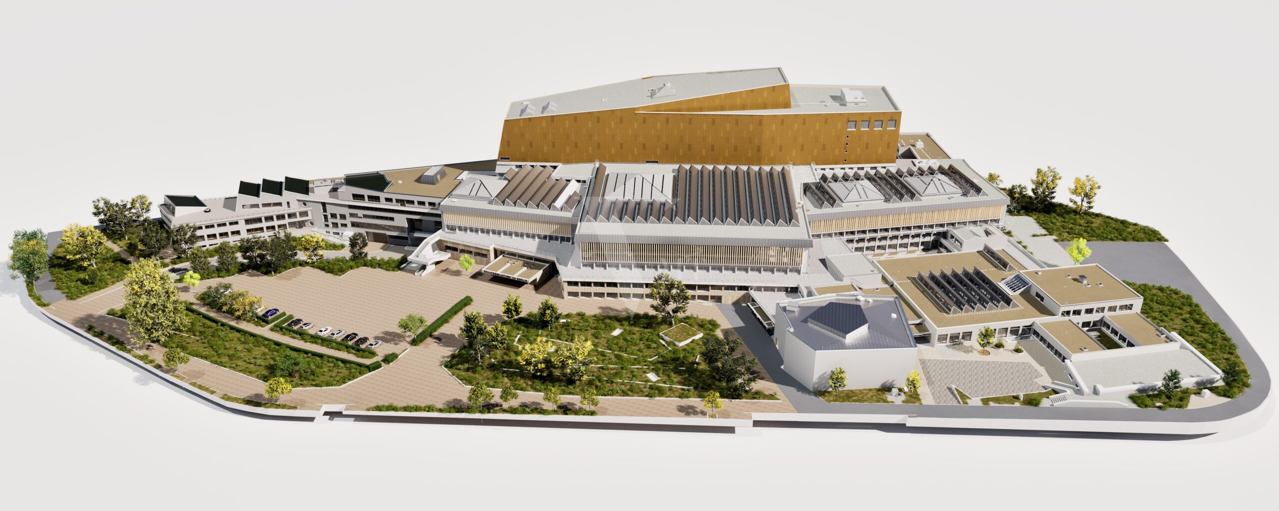
VMTS has delivered an increasing number of projects natively in Allplan for surveying offices, architecture firms, and engineering companies across the German-speaking region. The range covers simple residential buildings through to complex industrial facilities and historic structures.
Our approach: you scan — we handle all downstream modeling. From point cloud review through native Allplan modeling to QC report. On schedule, quality-assured, and scalable to your project volume.
If your office handles scan projects regularly and internal BIM modeling capacity is a constraint, we are glad to discuss a structured working relationship.
Frequently Asked Questions
Which point cloud formats can be processed?
We work with all common formats: E57, RCP, LAS, LAZ, XYZ, and PTX. For manufacturer-specific formats such as Faro FLS or Leica PTG, we recommend pre-conversion by the surveying office.
In which Allplan version is the model delivered?
We deliver in the Allplan version the client is currently using. Please provide your version number when placing the order.
Is a combined delivery possible — for example, Allplan for architecture and Revit for MEP?
Yes. We model interdisciplinary projects where different trades are delivered on different platforms. We handle coordination and IFC alignment.
How long does a typical Allplan modeling project take?
This depends on building size, complexity, and the agreed LOD. As a guideline: a single or multi-family residential building at LOD 300 can typically be delivered within five to ten working days. For larger projects we agree a binding delivery schedule upfront.
Contact
You have a point cloud and need a native Allplan model?
Describe your project briefly via our online form — we respond within one business day with an initial assessment.
Online form: Online Formulare
Email: hello@vmts.ch
WhatsApp:

VMTS — Scan-to-BIM partner for surveying offices and planning firms in the DACH region.
Revit · Archicad · Allplan · Vectorworks — natively modeled, delivered on schedule.
Nguyen Huynh (Rainer)
")
About the Author:
Nguyen Huynh (Rainer) is Managing Director at VMT Solutions, specializing in Point Cloud to BIM workflows for surveying, planning, and engineering offices. He focuses on precise BIM models, clearly defined quality standards, and long-term technical partnerships.
Related Posts

Recent Posts


Tag Cloud
We are proud to have
satisfied customers.
 Gerd Gindullis, Lecturer for digital as-built data capture at Aachen University of Applied Sciences, TerraMeta 3D Laser Service
 Stefan Schramm, Architekt Stefan Schramm
„Your plans are perfect; I’ve never seen anything like this before. These are drawings of the highest quality, I must say. I want to express my sincere thanks once again for your work.“
 Endre Szokolai, Digitalplan-Szokolai
VMT modeled a large industrial building in 3D for our research project. We provided DWG plans to VMT, and they delivered a highly detailed model, including the building envelope, interior walls, openings, and stairs. We had previously contracted a German company for the same object, but unfortunately, it didn’t work out. I was relieved and pleased that VMT handled it so reliably. Thank you for the excellent work and the truly fair price!

Very reliable company, courteous staff, and top-quality work. Our plans were created quickly and accurately. Thank you for that. Highly recommended.

Excellent advice and high 3D modeling quality at a great price-performance ratio… What more could you want? I can highly recommend them…